- Energy Micro EFM32 "Tiny Gecko" Developer Board - Impressions and open source tools usage thinking
- EFM32STK linux toolchain - Blogpost on using EFM32STK under Linux
- https://launchpad.net/gcc-arm-embedded - Cortex-M targeted toolchain from Ubuntu developers, binary tarball releases
- J-Link downloads -Tools/drivers for JTAG/SWD controller as included in EFM32STK boards, including for Linux
- EnergyMicro downloads - Official EnergyMicro downloads, including Linux tools
Sunday, December 9, 2012
Links for December 2012
Tuesday, September 11, 2012
Links for September 2012
- Arduino-IRremote multi-protocol IR library
- MSP430G2xxx parametric search (also, parametric search for other TI MCU families)
Monday, August 13, 2012
Links for August 2012
- Using native Android USB Host API - kind of libusb within Android.
- USB Host for Nook Simple Touch Reader
- ELLCC - Project to bring decent cross-compiling support to LLVM (currently cross-compiling is rather neglected by LLVM mainline)
- Blueman - GTK+ Bluetooth Manager
- hidclient - Forward local input devices via Bluetooth HIDP
- Using the PlayStation 3 controller in Bluetooth mode with Linux - This is about "Sixaxis" game controller, not BD Remote, but confirms that PS3 likes adhoc pairing stuff instead of true Bluetooth one.
Wednesday, July 4, 2012
TI Launchpad 1.4 vs 1.5 pin swappery
Everyone knows that AVR is the king of open-hardware/hobbyist hill, as well as one of the most available MCU family, with most popular MCUs easily sourceable around the world in the nearest half-decent electronic component shop/martetplace. Why would you want to swap Arduino-thingy for something else? Many factors would need to play for that to happen, like price, availability again, and some issues with AVR.
Texas Instruments with Launchpad devel board for MSP430 value line pushes edge on price and availability, shipping candy to almost any country in the world for unbelievable price. And one of the issue I had with AVR MCU is inconsistency in their implementation (pin and register maps), which complicates MCU upgrade and code portability among the models.
So, MSP430 delivered with Launchpad felt like fresh air, and overall pretty cleverly and attentively designed MCU. Well, as folks who watch that space know, TI replaces the original Launchpad 1.4 model which shipped with MSP430G2231 with 1.5, shipping with MSP430G2553, without changing the price, which felt like generous move, and their desire to become real Arduino competetor.
Well, one of the issue which came with 1.5 was that it turns out that MSP430G2553 uses swapped assignment of RXD & TXD pins in its hardware UART comparing to (completely software-based) UART implementation with MSP430G2231. That could raise some eyebrows: because 1) couldn't Launchpad designers be attentive and design it originally as being compatible with entire MSP430G family (i.e. use hardware UART pin assignment right away); 2) if it really happens that MSP430G2553 was designed after Launchpad 1.4, couldn't TI engineers be so attentive to be compatible with existing UART pin assignment in their advertisement product, based on which quite a few people may judge entire MSP430 family.
But OK, stuff happens. TI was kind enough to provide a workaround to swap pins using a jumper trick. And well, you mostly use UART to communicate with "big" computer, so that jumper there was the only thing need.
And few days ago I ported my code to communicate with an SPI device (using a shield) from G2231 to G2553. First issue is that former vs latter use completely different SPI (etc.) communication controllers - USI vs USCI (yup, could have been named clearly to emphasize their difference). So, I was hit by the same issue I blamed on AVR - well, there at least if there's SPI controller, it works the same, even if some register addresses/bits might be different.
But once I ported software, I still couldn't get my device working, and it took few hours to check thru datasheets and manuals to find out that G2231 vs G2553 have also MOSI vs MISO pins swapped! Now, that's something to really frown about. It's not some random software-emulated UART pins misplaced on G2231 and corrected on G2553. In case of SPI, both MCUs have hardware SPI, so swapping pins is just that - big unfriendly "surprise" delivered in hardware developer's face. It would be too naive to think that it again happened by accident or mistake - conspiracy theorist would say it was carefully managemented and engineered incompatibility within family, designed to make users keep buying old low-power stuff and disallow easier upgrades. It's pure wonder they didn't get an idea to swap VCC and GND - indeed why not, few hundreds/thousands MCUs/devices burnt, and happy customers come back to buy more.
Aftermath of SPI swap is actually more serious than UART swap - again, UART is mostly used to connect to host, so you can set needed jumper position on it and forget (scalable solution is to keep using software UART and original pin assignment, as hardware UART is absent on quite a few devices and Launchpad is limited to 9600 baud anyway). But SPI is peripheral interface and the whole idea of Arduino and which TI also seems to push to Launchpad is extension modules aka shields. And SPI swappery means if you "just" make a shield for SPI device, it won't compatible with either old or new device (on hardware level). Would be pretty serious issue for folks who try to support Launchpad ecosystem, but surprisingly I found only one post on the issue, which again, means that folks are not aware, and unhappy customers may follow.
So, it's hard to say if TI should be blamed or vice-versa, thanked for being fare and show with Launchpad not only boons, but also drawbacks of MSP430 family. What's important are lessons learned (not just with this case, but with few other Launchpad hiccups):
- Launchpad is not an Arduino.
- Launchpad will not be an Arduino.
- If you want nicely-working and user-friendly devel board, Arduino is always there.
- If you want something cheap, Launchpad so far there too.
- Expect Launchpad to bring issues and surprises, and break with new versions (ultimately, its price may break).
- MSP430 is unlikely to displace AVR.
- If you want to try MS430, check its availability. For example, in this part of the world, it's not possible to source small quantities of MSP430 value line, because well, nobody will get an idea to replace trusty ATtiny, so it makes no sense to bring them to shops. And nobody would get an idea to replace ATtiny because:
- "Didn't break - didn't fix it." If ATtiny can do it, why bother with something else. That's not just inertness of thought, which industry/experienced people possess, that's actually proved by experience, as we saw. To change that, new product should do it much better than existing, but MSP430 doesn't want to do that.
Saturday, June 23, 2012
KiCAD the schematic/PCB design suite
As many folks who start with hobby electronics design, I started with Eagle, because that's what most of other folks seem to use. I was able to produce a simple board, but fairly speaking, I have mixed feelings about it - both UI, structure, and functionality could be better.
I didn't try KiCAD right away because I read lot of (apparently old, or FUDish) notes that it lacks basic features, unstable, and complicated. I finally got to try fairly recent version of KiCAD and was astonished how logical, fairly easy to use, and well-performing it is. Yes, it is still could do better, for example, it's hard to understand what precludes to use direct manipulation GUI, where you can drag an object with ... dragging an object with mouse, but at least commands for manipulation are standard, complete, and available via context menu. So, doubts off, KiCAD should be *the* toolkit for Open Hardware.
So, what are the outstanding features of KiCAD?
Of course, its standard library contains all/most discrete components. Next, for infinite number of ICs, you don't need to draw each of them in all possible and impossible packages - there's finite number of packages, KiCAD already has great selection of, and you can create missing once and reuse it for new chips very easily. Secondly, a schematic symbol for a chip is a rectangle with pins sticking out of it, so to "create" a new chip, only pin names needed, the rest can be easily scripted thanks to text-based format (and there're existing tools, albeit they don't seem to be open-source).
Now few notes about installing. Current version of Ubuntu ship rather old (one-year as of writing) version of KiCAD, only upcoming Quantal ships (as of now) 0.20120526+bzr3261-1, and that's what I downloaded and installed manually on Precise (12.04) without any issues. There's also daily builds from trunk, and that's what I'm going to try next, just wanted to start from a known stable reference. So far, I had one crash with 0.20120526+bzr3261-1, without any adverse effects.
Don't forget to install package kicad-doc-en. Unfortunately, Quantal's version still includes older version of tutorial, you need latest version called "Getting_Started_in_KiCad.pdf", you can find it here. Following the tutorial will give you complete walkthru of KiCAD workflow, enough to produce your boards, including custom components.
I didn't try KiCAD right away because I read lot of (apparently old, or FUDish) notes that it lacks basic features, unstable, and complicated. I finally got to try fairly recent version of KiCAD and was astonished how logical, fairly easy to use, and well-performing it is. Yes, it is still could do better, for example, it's hard to understand what precludes to use direct manipulation GUI, where you can drag an object with ... dragging an object with mouse, but at least commands for manipulation are standard, complete, and available via context menu. So, doubts off, KiCAD should be *the* toolkit for Open Hardware.
So, what are the outstanding features of KiCAD?
- Separation of schematic symbol vs PCB footprint - they are not linked in the component library, but instead are linked as part of PCB design process
- Text-based formats for all files
Of course, its standard library contains all/most discrete components. Next, for infinite number of ICs, you don't need to draw each of them in all possible and impossible packages - there's finite number of packages, KiCAD already has great selection of, and you can create missing once and reuse it for new chips very easily. Secondly, a schematic symbol for a chip is a rectangle with pins sticking out of it, so to "create" a new chip, only pin names needed, the rest can be easily scripted thanks to text-based format (and there're existing tools, albeit they don't seem to be open-source).
Now few notes about installing. Current version of Ubuntu ship rather old (one-year as of writing) version of KiCAD, only upcoming Quantal ships (as of now) 0.20120526+bzr3261-1, and that's what I downloaded and installed manually on Precise (12.04) without any issues. There's also daily builds from trunk, and that's what I'm going to try next, just wanted to start from a known stable reference. So far, I had one crash with 0.20120526+bzr3261-1, without any adverse effects.
Don't forget to install package kicad-doc-en. Unfortunately, Quantal's version still includes older version of tutorial, you need latest version called "Getting_Started_in_KiCad.pdf", you can find it here. Following the tutorial will give you complete walkthru of KiCAD workflow, enough to produce your boards, including custom components.
Thursday, May 10, 2012
Solar cell types and their looks
Following cool solar experiments at jeelabs.org, I also got idea to attach something to a solar cell. But first, figure out what types of them exists and available. Regarding the first, you can read in Wikipedia. But that's example of dried-out wikipedia article, giving a lot of formal facts, but little practical knowledge. What I'd like to know is what types are typically available in small consumer products.
Here's what I researched. First type is brownish, with regular vertical or horizontal lines. It's the type of solar cell which have been see for at least 20 years in calculators. So, that's amorphous silicon solar cell, less expensive (explains why we had it for 20 years around) and less efficient, they say. But they also say that there're special subtypes, designed to work in low-light conditions (specifically, provide enough voltage, even though current may be miniscule). Here's how it typically looks:

Last years, another type became widely available in cheap stuff - crystalline silicon solar cells. In cheap stuff, they look like black (or dark) colored plate, covered with few millimeter of something like epoxy, in which you can clearly see metal wires - oftentimes in irregularly spaced groups. Looking closely, it can be seen that epoxy actually holds individual bars of crystalline silicon, and irregular spacing of builtin wires are in particular due to irregular cuts of these bars in the original wafer.
Here's close up:
 They say that crystalline is more efficient than amorphous, but more expensive. Explains why we started to see it around much later than amorphous. There's also mono-crystalline and poly-crystalline varieties, the first being more expensive, so my guess is that in cheap stuff we have poly-crystalline. It appears that small-size crystalline are rated for smaller voltage (2v) than an amorphous, which you can find for ~5V.
They also say that under dimmer lighting, crystalline cells provides reduced voltage.
Here's what I researched. First type is brownish, with regular vertical or horizontal lines. It's the type of solar cell which have been see for at least 20 years in calculators. So, that's amorphous silicon solar cell, less expensive (explains why we had it for 20 years around) and less efficient, they say. But they also say that there're special subtypes, designed to work in low-light conditions (specifically, provide enough voltage, even though current may be miniscule). Here's how it typically looks:
Last years, another type became widely available in cheap stuff - crystalline silicon solar cells. In cheap stuff, they look like black (or dark) colored plate, covered with few millimeter of something like epoxy, in which you can clearly see metal wires - oftentimes in irregularly spaced groups. Looking closely, it can be seen that epoxy actually holds individual bars of crystalline silicon, and irregular spacing of builtin wires are in particular due to irregular cuts of these bars in the original wafer.
Here's close up:

They also say that under dimmer lighting, crystalline cells provides reduced voltage.
Wednesday, May 9, 2012
"Arduino Hosted" Python Module
Here's what I've been hacking for some time now - a Python module which allows to run Arduino, etc. code on a host computer, while still allowing to access Arudino (etc.) hardware.
Of course, this is very obvious idea, so announcement of such project should proceed with explaining why yet another one? Two requirements I had was: using human readable/writable underlying protocol for communication with the board and being as much as possible compatible with original Arduino API/syntax. Regarding the latter, Arduino wiki's Interfacing/Python lists few modules which allow to control Arduino from Python, but you may find it amusing how they go out of their way to deviate from standard Arduino API (I saw as funky stuff as "board.digital[13].write(1)", but even the humblest has digital_write() instead of digitalWrite()). On the contrary, with Arduino Hosted, standard Blink example looks like:
from arduino import *
def setup():
pinMode(LED, OUTPUT)
def loop():
digitalWrite(LED, HIGH)
delay(1000)
digitalWrite(LED, LOW)
delay(1000)
arduino.run(globals())
That's pretty direct translation of C code (plus few idioms), and directly translatable back to C. And that's idea - you prototype and debug code in hosted environment, and then can easily translate it to native code (to keep debugging on, because latency of of hosted and native execution is quite different which hides/adds lots of timing issues).
Regarding the board communication protocol, I knew about BusPirate before that, and was really happy to find Joby Taffey's BusNinja implementation for Arduino. Even more, I found the implementation for TI Launchpad from the same author (Launchpad's version somehow named "SPI Explorer"). So, BusPirate's protocol with extensions is what I based on. Of course that doesn't too well, especially with TI Launchpad, which has particularly crippled UART support. Other issue is that BusPirate (even binary protocol version) supports working with only one bus at time. That's fine for BusPirate's original purpose, but limiting for a project like this (well, so far I didn't have to use I2C and SPI at the same time).
What about Firmata? First of all, it doesn't support SPI, and working with SPI devices was the immediate need behind implementing this module. Secondly... Well, there's a saying "If the only thing you know is a hammer, then any thing around looks like a nail." That's must have been the idea behind designing a MCU control protocol basing on MIDI protocol. NO WAI.
#!/usr/bin/env python
import arduino
arduino.init(debug=True)import arduino
from arduino import *
def setup():
pinMode(LED, OUTPUT)
def loop():
digitalWrite(LED, HIGH)
delay(1000)
digitalWrite(LED, LOW)
delay(1000)
arduino.run(globals())
That's pretty direct translation of C code (plus few idioms), and directly translatable back to C. And that's idea - you prototype and debug code in hosted environment, and then can easily translate it to native code (to keep debugging on, because latency of of hosted and native execution is quite different which hides/adds lots of timing issues).
Regarding the board communication protocol, I knew about BusPirate before that, and was really happy to find Joby Taffey's BusNinja implementation for Arduino. Even more, I found the implementation for TI Launchpad from the same author (Launchpad's version somehow named "SPI Explorer"). So, BusPirate's protocol with extensions is what I based on. Of course that doesn't too well, especially with TI Launchpad, which has particularly crippled UART support. Other issue is that BusPirate (even binary protocol version) supports working with only one bus at time. That's fine for BusPirate's original purpose, but limiting for a project like this (well, so far I didn't have to use I2C and SPI at the same time).
What about Firmata? First of all, it doesn't support SPI, and working with SPI devices was the immediate need behind implementing this module. Secondly... Well, there's a saying "If the only thing you know is a hammer, then any thing around looks like a nail." That's must have been the idea behind designing a MCU control protocol basing on MIDI protocol. NO WAI.
Monday, April 2, 2012
OpenSource Sensor Node firmware for BlueCore-based Bluetooth Modules
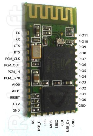
BlueCore4-Ext is a popular Bluetooth chip used in many Bluetooth modules, some priced below $10. The idea is to create Wireless Sensor/Control Network using this modules, as Bluetooth is really ubiquitous technology nowadays, so any smartphone can be used to provide user UI/control for such network. This is especially facilitated by the fact that BlueCore4-Ext is a SoC (system-on-chip) integrating microcontroller and peripherals in one package (small too), allowing it to be programmed with a user firmware for autonomous functioning with minimum of additional components. It even has built-in temperature sensor, so just add a battery and you have ready-made wireless temperature sensor (not too precise, granted, but you can calibrate it yourself ;-) ).
(Image by robocraft.ru)
BluTuNode is a firmware for such a Bluetooth Wireless Node, which allows to control it from a host over the air.
Source code: http://github.com/pfalcon/blutunode
Features implemented:
Appendix:
Some technical characteristics of BC4-based module:
SoC: BC417 (BC417143B full model ID)
CPU: XAP2+, 16-bit RISC (no special 8-bit data support), Harward architecture, 64Kword data space, 1Mword+ code space
Flash: 1Mbyte (512Kwords, 75% typically occupied by Bluetooth stack/OS)
RAM: 24Kword
Execution environment: Virtual machine, no native hardware access (later versions of firmware OS support "native" mode, heavily bounds-checked still).
(Image by robocraft.ru)
BluTuNode is a firmware for such a Bluetooth Wireless Node, which allows to control it from a host over the air.
Source code: http://github.com/pfalcon/blutunode
Features implemented:
- Full control of GPIO: input/output, configuring direction, pullups/pulldowns, etc.
- Reading sampled from build ADCs.
- Reading of temperature sensor.
- Querying other system parameters.
- Querying Bluetooth parameters.
- Poll mode, when module automatically reads some sensor at specified period and sends information to host.
- UART control (note that this is generally not a priority, because UART is mostly used to connect to host/microcontroller, and this firmware is designed for autonomous modules).
- SPI/I2C/1-wire support to connect external sensors.
- More Bluetooth-level information and control.
- OpenSource tools to program/manage BlueCore modules.
- Flash access/writing, over-the-air firmware updates.
Appendix:
Some technical characteristics of BC4-based module:
SoC: BC417 (BC417143B full model ID)
CPU: XAP2+, 16-bit RISC (no special 8-bit data support), Harward architecture, 64Kword data space, 1Mword+ code space
Flash: 1Mbyte (512Kwords, 75% typically occupied by Bluetooth stack/OS)
RAM: 24Kword
Execution environment: Virtual machine, no native hardware access (later versions of firmware OS support "native" mode, heavily bounds-checked still).
Thursday, March 29, 2012
Developing for TI LaunchPad MSP430 board on Ubuntu
If you google for it, you'll find quite a few blog posts, but most of them are from 2010. But starting with Ubuntu 11.10 (Oneiric), gcc-msp430 and friends are included in the main repositories, so you can just apt-get install them:
There's one annoying bug in Oneiric's version of binutils-msp430 which breaks build with -ffunction-sections -Wl,--gc-sections options (which is kinda common trick in embedded world to remove unused functions and reduce code size): mspgcc #3386145. It is fixed in Ubuntu 12.04 (Precise).
I'm however still running Maverick, so instead I downloaded following Oneiric packages:
Then few from Precise:
(If you try to install Precise versions of other packages on Maverick, they want to pull upgrades to system libs, which I wanted to avoid).
and installed them manually with dpkg.
apt-get install binutils-msp430 gcc-msp430 \
    msp430-libc msp430mcu mspdebug
There's one annoying bug in Oneiric's version of binutils-msp430 which breaks build with -ffunction-sections -Wl,--gc-sections options (which is kinda common trick in embedded world to remove unused functions and reduce code size): mspgcc #3386145. It is fixed in Ubuntu 12.04 (Precise).
I'm however still running Maverick, so instead I downloaded following Oneiric packages:
binutils-msp430_2.21~msp20110421-2_i386.deb
gcc-msp430_4.5.3~mspgcc-4.5.2-20110612-1_i386.deb
libgmp10_5.0.1+dfsg-7ubuntu2_i386.deb
libmpc2_0.9-3_i386.deb
msp430-libc_20110612-1_i386.deb
mspdebug_0.16-1_i386.deb
Then few from Precise:
binutils-msp430_2.22~msp20110716p5-1_i386.deb
msp430mcu_20110613-3_all.deb
(If you try to install Precise versions of other packages on Maverick, they want to pull upgrades to system libs, which I wanted to avoid).
and installed them manually with dpkg.
Wednesday, March 28, 2012
Connetcing to preprogrammed TI Launchpad demo under Linux
TI Launchpad board comes with preprogrammed demo application for temperature sensing which is touted to output temperature values to host via USB-encapsulated UART. By connecting to it via terminal you can see that it indeed sends something, but that doesn't look anything like temperature represent in ascii digits, like someone naively could expect. It turns out that it's well kept secret on Launchpad wiki pages how to make sense out of it - at least, you get advertisements for CCS and Java-based GUIs to read out the output, but not straight docs of how to use builtin demo without all those crutches. So well, wrong approach - it's your random user-friendly arduino, approach of reading docs doesn't work here, better go straight to the source.
And, here's step by step instructions:
First thing to note is that Launchpad's UART-via-USB emulation is extremely fragile. It seems that if MCU started to produce UART output but host doesn't read it out, then buffer in USB bridge just gets overflowed and it stops responding to USB. So, if you want to get it working, follow each step below precisely and if any issue happens, restart from beginning (with unplugging LaunchPad).
- If you have plugged LaunchPad into USB, unplug it now to make sure you start with properly reset device.
- Plugin the board into USB, general-purpose green and red should blink interchangeably. The demo app doesn't yet sense temperature or sends it out yet in this mode.
- Execute stty 2400 -F /dev/ttyACM0 . That's right - the demo app communicates at 2400 bit/s data rate and using any other rate will produce garbage input. (One reason for such low speed is that LaunchPad's MCU actually doesn't have hardware UART, it is emulated in software).
- Run hexdump -v -C /dev/ttyACM0 . It shouldn't produce any output yet.
- Press GPIO button. The demo app goes into measurement mode and starts to send out temperature in Fahrenheit as raw bytes over UART. Try to heat/cool air around the board to see values change.
00000020  60 60 60 60 60 60 60 60  60 60 60 60 60 60 60 60  |````````````````|
00000030  60 60 60 60 60 60 60 60  60 60 60 60 60 60 60 60  |````````````````|
00000040  60 60 60 60 60 60 60 60  60 60 61 60 60 61 60 60  |``````````a``a``|
00000050  61 60 60 61 61 61 60 61  61 61 61 61 61 61 61 61  |a``aaa`aaaaaaaaa|
00000060  61 61 61 61 61 62 61 62  62 62 62 62 62 62 62 61  |aaaaababbbbbbbba|
00000070  62 62 62 62 62 62 62 62  62 62 62 62 62 62 62 62  |bbbbbbbbbbbbbbbb|
00000080  62 62 62 62 62 62 62 62  62 62 62 62 62 62 62 62  |bbbbbbbbbbbbbbbb|
Monday, February 20, 2012
NSLU Optware for Android
Yes, there was kind of attempt at that already, but:
- It's no longer available at the link announced and spread over the Internet (yep, it's available at another, but why so ... complicated?)
- It ships binary blobs of unknown origin. Yup, maybe one could trace their origins, but who'd bother, and telepaths are on vacation as usual. It should be described stringently where they are from, if not scripted to be collected in user's build directory from known good sources, so users can actually trust them.
- It is marketed as supporting only something called "Nook Color". What's that, I thought it was Optware for Android? Could I have Optware specifically for my HP nx9420 notebook, serial number XYZZY, 3Gb of RAM? Just make sure it's different from the Optware for the same notebook, but with 4Gb of RAM, and from any other Optwares in the world!
- It goes as far as patching rootfs ramdisk. That may work on Nook Color or may brick it. That may work on next firmware upgrade of Nook Color or may brick. That may work on another device or may brick. The talk is not about this, it's about the fact that it's two big differences - to be able to install and run bash and to have sshd started automatically after the boot. I definitely want first, but I will do good consideration if/when I need second. So, I don't want setup for those 2 stages to mixed and done without myself being ready for stage 2.
- It still appears to rely on presence of some other 3rd party stuff (look at that #!/bin/sh line, there's no such thing on pristine Android device, only #!/system/bin/sh)
Sunday, January 29, 2012
HC-04 Bluetooth module and BlueCore4 Deep Sleep
The good news is that BlueCore indeed has Deep Sleep mode, it's not marketing hype. It can be verified by configuring PSKEY_CLOCK_REQUEST_ENABLE to drive PIO when chip uses/doesn't use external clock. The key here is not to keep PSTool run (which well, you need to tweak sleep settings).
The bad news is that an HC-04 module in Deep Sleep still consumes 2.5mA, which is far too high for anything called Deep Sleep. So, something on the module besides BlueCore still consumes too much power. However, when BlueCore is held in reset state, entire module consumes 0.
Without Deep Sleep, simple LED flash task consumes 3.5mA, so there's not that much gain from the Deep Sleep...
Enabling SPI logging in BlueSuite tools CSR BlueCore chips
BlueFlashCmd.exe and other tools, part of CSR BlueSuite toolset to program BlueCore Bluetooth chips, has support for logging SPI communication with a chip. To enable it:
The key parameter here is SPIDEBUG_FILE - logging is activated when it's specified, and thus logging is always done to a file. One way to have logging go to a console is to use SPIDEBUG_FILE=con: , but then it won't be possible to redirect it.
Besides SPIDEBUG=ON, there're other logging levels/features:
Looking at the output produced, it turns out it spends a lot in calibrating SPI speed, a way to that down is to use SPISLOW=ON setting right away.
BlueFlashCmd.exe -trans "SPIDEBUG_FILE=spi.log SPIDEBUG=ON" -chipver
The key parameter here is SPIDEBUG_FILE - logging is activated when it's specified, and thus logging is always done to a file. One way to have logging go to a console is to use SPIDEBUG_FILE=con: , but then it won't be possible to redirect it.
Besides SPIDEBUG=ON, there're other logging levels/features:
- SPIDEBUG
- SPIDEBUG_REPRODUCIBLE
- SPIDEBUG_WRITES
- SPIDEBUG_READS
- SPIDEBUG_WIRE
Looking at the output produced, it turns out it spends a lot in calibrating SPI speed, a way to that down is to use SPISLOW=ON setting right away.
Tuesday, January 17, 2012
Notes on Android EGL/native windowing system interface
EGL is defined here and appears to be in OpenGL ES something what GLUT was (?) in OpenGL world. At least, EGL is what takes care of actually displaying on screen what was rendered by OpenGL ES.
Donut
EGLNativeWindowType is defined in opengl/include/EGL/eglplatform.h as struct egl_native_window_t* . egl_native_window_t is defined nearby in opengl/include/EGL/eglnatives.h . This is nice, clean, standalone structure (unlike horror in Eclair+). It starts with a "magic" (signature) 0x600913, followed by "version" which is sizeof of the structure (now I know why Microsoft gets a buck on each Android phone sold - they for sure patented this (stupid? lazy?) trick widely used in Win32 API). There're some function pointers (virtual method table) used by EGL to call into native windowing system (deep, close to vendor drivers) to support its workings. Out of these, there's essentially one related to rendering finalization: swapBuffers(). So yes, it seems that eglSwapBuffers() just calls out to this. The structure also directly contains "Base memory virtual address of the surface in the CPU side" and other easily graspable memory/graphics notions.
It's clear that in its young years, Android was fair and naive, not suitable at all for typical vendor OpenGL mumbo-jumbo. The "fix" came with the later versions.
Eclair and following
EGLNativeWindowType is defined (in include/EGL/eglplatform.h) to be struct ANativeWindow*. ANativeWindow was android_native_window_t in Eclair, but was renamed to ANativeWindow in Froyo (android_native_window_t is still available for compatibility). ANativeWindow is defined in platform/frameworks/base/include/ui/egl/android_natives.h:
ANativeWindow not just emulates VMT, but seems to want to do entire C++ in C-like manner in its metes and bounds. It uses subclassing from android_native_base_t, and that contains fields for magic ("_wnd" for ANativeWindow) and version-sizeof. Methods defined are also more involved. Among the most interesting are dequeueBuffer(), lockBuffer(), queueBuffer(). Essentially, it appears that EGL takes a free buffer out of native system's rotation, locks it for changing its contents, then puts back into queue for display.
Actual implementation of ANativeWindow for read device screen is in libs/ui/FramebufferNativeWindow.cpp . There's factory function to get its instance: android_createDisplaySurface().
All implementation details on buffers used are hidden in android_native_buffer_t type. It is also subclassed from android_native_base_t, its magic is "_bfr". Among simple things like width/height it contains buffer_handle_t, which leads in utero of vendor graphics driver. buffer_handle_t is native_handle*, and native_handle is a generic container for arbitrary number of fd's and pointers.
native_handle's are produced by gralloc vendor module, and that's exactly what FramebufferNativeWindow constructor does - it loads gralloc module, then uses it to open framebuffer and gralloc devices. It then allocates back and front buffers from gralloc devices with the size of the framebuffer. queueBuffer() method is implemented by calling framebuffer's post() method which well, shows the buffer on the screen.
Thoughts/notes on Android version upgrades and reusing Android drivers
So, what it takes to upgrade Android on an arbitrary Android device (from user perspective)? What takes to run Linux in full-fledged mode? This boils down to few things:
Kernel porting
Upgrade kernel. This means forward-porting hardware support modules to a new kernel version. That's, when source code for such modules is available. Sometimes, it's not violating GPL (or tainting kernel, but who wants that? ;-) ). In an ideal world, that would all that's needed, but vendors don't like GPL, and try to move stuff outside of kernel. So, the list continues.
Bitblt acceleration porting
Next step is making sure that basic hardware acceleration works - accelerated bitblt/compositing (defining compositing as bitblt with alpha). This is actually pretty important step - without accelerated bitblt, Android with more or less big screen will run pretty sluggishly. Well, X Windows won't run too zippy either. Bitblt code in Android lives in /system/lib/hw/copybit.*.so and depends on gralloc.*.so from the same dir (* there is vendor/implementation identifier - Android support multiple, pluggable implementations). Needless to say, for a random device, source for these modules are not available - vendors don't have to provide it, it's Apache2-licensed, and very few choose to uphold OpenSource spirit nonetheless. So, if new Android version have changes the ABI for those modules, then oops - upgrade is "not possible" is layman terms. Of course, real men will immediately think about writing adapters, etc...
What about other X and other "foreign" windowing systems? They would need drivers/adapters too, and base all their low-level FB access based on Android's gralloc/bitblt/etc. model.
OpenGL ES porting
Last, least, but nonetheless. Curse of the modern world - OpenGL. You didn't have it on your Apple 2 (I mean Apple 2, yes, not what you thought about!) and everything was great, wasn't it? Apart from games you don't have time to play, what it's useful for? Yes, as soon as we'll stream videosignal directly into the brain, it will be useful for augmented reality, but I mean, *useful now*. They keep talking they added some hardware acceleration using OpenGL to the normal UI, then immediately say it didn't work that great, and depends on many things, because... Because OpenGL simply doesn't work that great, yeah. For example, even "accelerated", it's pretty slow, buggy, inconsistent across devices, etc, etc.
Anyway, thanks for listening to the rant. Let's de-emphasize usefulness of OpenGL, let's just take it as a challenge - vendors hacked it, so why can't hackers hack it? The basic idea is the same as with bitblt - there's an interface between closed vendor OpenGL ES implementation and Android. If interface changed, you're hosed. I mean, you write adapters. You also write adapters to make it talk with your windowing system of choice, and not Android. The core interfacing part of OpenGL ES/Android junction is EGL. How to deal about it is worth a separate post.
New Hack Toy - Zenithink ZT-180
Recently I got new hack toy: cheap (well, depends) Chinese Zenithink ZT-180 tablet. This one seem to be (have been) pretty popular and hacker-friendly. Here's data about it:
Button combinations to hold during power on:
Random links:
- Vendor: http://zenithink.com/
- Product home page, ZT180-102 (it's the oldest in the product list, so soon will go to "Retired products" (== /dev/null))
- CPU: IMAPx200 (or IMAPx210, IMAPx220), ~1GHz
- GPU (SoC-builtin): GC600 (tentative)
- RAM: 512MB (Android boots with mem=384M)
- Bootloader: u-boot
- Kernel source from the vendor (github)
- Slatedroid forum announcement and discussion about the kernel release above
- Vendor toolchain
- Post saying that user yuray started upgrading kernel to 3.0.4. Following posts add more details, no source link provided.
- yuray also appears to be the author of ZT-180-Linux-Flash-Tool.
- Slatedroid ZT-180 Wiki
- More detailed hacking information
Button combinations to hold during power on:
- Home+Power - Upgrade firmware from /sdcard/zt-update/
- Left arrow (of swing double-button)+Power - Boot with debug kernel from /sdcard/zt-debug/ . Debug kernel is booted and continues with the normal boot process.
- Right arrow (of swing double-button)+Power - Multiboot support, select one of 3 modes:
- Android adb - kernel with ADB over USB support
- Android mass storage - kernel with mass storage USB gadget support (tablet is presented as a mass storage when connected to host)
- Other OS - WinCE
Random links:
- http://www.slatedroid.com/topic/10233-zenithink-zt-180-cpu-actually-infotmic-imap210-cpu/
- http://www.androidtablets.net/forum/infotmic-based/2354-infotmic-chips.html
Monday, January 16, 2012
Stopping Android GUI services
Well, this really worth a cross-post. The way to stop Android GUI services is (under root of course):
UPDATE: Thanks to hint from StackOverflow: there're even simpler commands: "start" & "stop". Surprise.
setprop ctl.stop zygote
UPDATE: Thanks to hint from StackOverflow: there're even simpler commands: "start" & "stop". Surprise.
Saturday, January 7, 2012
Bluetooth Park Mode Exposed
So well, as I settled on Bluetooth as a wireless sensor/automation protocol and grow my device base, I started to wonder what will happen when I'll have more than 7 slave devices. Bluetooth stack of master device (Bluez in our case) must be smart to put devices into and out of PARK mode to allow to communicate with more than 7 devices, right? Not in this world.
Not only Bluez doesn't support park management, according to Marcel Holtmann, the problem is that it's really not known if there're devices (masters) which can support more than very limited number of slaves, or even have decent park mode implementation at all:
HC-04 Bluetooth module with CSR BlueCore4-Ext
< ACL 00:11:10:xx:xx:xx handle 12 state 8 lm MASTER
What we need here is a connection handle 12 (0x0c). hcitool doesn't have dedicated command for part mode (and for lot of other things), so we'll use raw HCI command mode using "cmd" command:
# hcitool cmd --help
Usage:
cmd <ogf> <ocf> [parameters]
Example:
cmd 0x03 0x0013 0x41 0x42 0x43 0x44
What's important here is that <parameters> should be byte values. If words should be given as parameters, they should be give by bytes in little-endian format.
Here we run HCI_Park_State(Connection_Handle=0x000c, Beacon_Max_Interval=0x0050, Beacon_Min_Interval=0x0040) command (see Bluetooth spec). And here's communication as captured by hcidump (parts irrelevant to park command omitted):
2012-01-07 15:36:46.084074 < HCI Command: Park State (0x02|0x0005) plen 6
handle 12 max 80 min 64
2012-01-07 15:36:46.086040 > HCI Event: Command Status (0x0f) plen 4
Park State (0x02|0x0005) status 0x00 ncmd 1
2012-01-07 15:36:46.271047 > HCI Event: Mode Change (0x14) plen 6
status 0x24 handle 12 mode 0x00 interval 0
Error: LMP PDU Not Allowed
This "LMP PDU Not Allowed" was quite confusing and took me lot of googling to figure out. Fortunately, I found insightful post from a CSR guy right on this matter: http://article.gmane.org/gmane.linux.bluez.devel/72
What we get here is that local Bluetooth master just forwards status it got from the remote device. As the message suggests, park might be disabled in remote device line policy. Let's see:
# hcitool cc 00:11:10:xx:xx:xx; hcitool lp 00:11:10:xx:xx:xx
Link policy settings: RSWITCH HOLD SNIFF PARK
Here's slight issue of what hcitool lp actually does. According to man, it "displays link policy settings for the connection to the device with Bluetooth address". There's also "hcitool lp" command which "Sets default link policy". So, reasonable assumption would be that every device may have default link policy, then during connection, they negotiate link policy which is suitable for the connection. Ok, let's set PARK policy explicitly:
But hcidump shows the the same "LMP PDU Not Allowed" error. So, what we have is that HC-04 module advertizes park support, it apparently negotiates its availability for connection, but when asked to actually perform it, it rejects it. This is so much correlates with this message: http://article.gmane.org/gmane.linux.bluez.user/12710
PS3 Bluetooth remote
So, this fair Broadcom device doesn't even conceal the fact that it's barely Bluetooth interoperatable - it doesn't support park state at all.
No surprises when asking it to go there nontheless:
2012-01-07 16:03:08.863586 < HCI Command: Park State (0x02|0x0005) plen 6
handle 13 max 80 min 64
2012-01-07 16:03:08.865636 > HCI Event: Command Status (0x0f) plen 4
Park State (0x02|0x0005) status 0x1a ncmd 1
Error: Unsupported Remote Feature / Unsupported LMP Feature
LG KS20 WindowsMobile phone
# hcitool info 00:1E:75:xx:xx:xx | grep park
<park state> <RSSI> <channel quality> <SCO link> <HV2 packets>
So, this one advertizes park. But:
2012-01-07 16:29:11.288514 < HCI Command: Park State (0x02|0x0005) plen 6
handle 12 max 80 min 64
2012-01-07 16:29:11.290485 > HCI Event: Command Status (0x0f) plen 4
Park State (0x02|0x0005) status 0x00 ncmd 1
2012-01-07 16:29:11.466508 > HCI Event: Mode Change (0x14) plen 6
status 0x0c handle 12 mode 0x00 interval 0
Error: Command Disallowed
Broadcom is such Broadcom...
Huawei U8160 aka Vodafone 858 Smart Android phone
# hcitool info 04:C0:6F:xx:xx:xx | grep park
Broadcom is such Broadcom...
HTC Mogul WindowsMobile phone
Bwahaha! TI rules!
Manufacturer: Cambridge Silicon Radio (10)
2012-01-07 17:54:17.141466 < HCI Command: Park State (0x02|0x0005) plen 6
handle 12 max 80 min 64
2012-01-07 17:54:17.142911 > HCI Event: Command Status (0x0f) plen 4
Park State (0x02|0x0005) status 0x00 ncmd 1
2012-01-07 17:54:17.472919 > HCI Event: Mode Change (0x14) plen 6
status 0x00 handle 12 mode 0x03 interval 80
Mode: Park
Park mode work here, supervised by Bluez.
So, out of 7 devices (that's whole piconet, and I have more!) only 3 supported park mode.
More insightful posts:
Not only Bluez doesn't support park management, according to Marcel Holtmann, the problem is that it's really not known if there're devices (masters) which can support more than very limited number of slaves, or even have decent park mode implementation at all:
- http://article.gmane.org/gmane.linux.bluez.devel/287
- http://article.gmane.org/gmane.linux.bluez.user/3813
- http://article.gmane.org/gmane.linux.bluez.user/3815
- http://article.gmane.org/gmane.linux.bluez.user/6032
- http://article.gmane.org/gmane.linux.bluez.user/12689
- http://article.gmane.org/gmane.linux.bluez.user/12719
- http://article.gmane.org/gmane.linux.bluez.devel/13135
HC-04 Bluetooth module with CSR BlueCore4-Ext
# hcitool cc 00:11:10:xx:xx:xx; hcitool con
Connections:< ACL 00:11:10:xx:xx:xx handle 12 state 8 lm MASTER
What we need here is a connection handle 12 (0x0c). hcitool doesn't have dedicated command for part mode (and for lot of other things), so we'll use raw HCI command mode using "cmd" command:
# hcitool cmd --help
Usage:
cmd <ogf> <ocf> [parameters]
Example:
cmd 0x03 0x0013 0x41 0x42 0x43 0x44
What's important here is that <parameters> should be byte values. If words should be given as parameters, they should be give by bytes in little-endian format.
# hcitool cc 00:11:10:xx:xx:xx; hcitool cmd 0x02 0x05 0x0c 0 0x50 0 0x40 0
Here we run HCI_Park_State(Connection_Handle=0x000c, Beacon_Max_Interval=0x0050, Beacon_Min_Interval=0x0040) command (see Bluetooth spec). And here's communication as captured by hcidump (parts irrelevant to park command omitted):
handle 12 max 80 min 64
2012-01-07 15:36:46.086040 > HCI Event: Command Status (0x0f) plen 4
Park State (0x02|0x0005) status 0x00 ncmd 1
2012-01-07 15:36:46.271047 > HCI Event: Mode Change (0x14) plen 6
status 0x24 handle 12 mode 0x00 interval 0
Error: LMP PDU Not Allowed
This "LMP PDU Not Allowed" was quite confusing and took me lot of googling to figure out. Fortunately, I found insightful post from a CSR guy right on this matter: http://article.gmane.org/gmane.linux.bluez.devel/72
What we get here is that local Bluetooth master just forwards status it got from the remote device. As the message suggests, park might be disabled in remote device line policy. Let's see:
# hcitool cc 00:11:10:xx:xx:xx; hcitool lp 00:11:10:xx:xx:xx
Link policy settings: RSWITCH HOLD SNIFF PARK
Here's slight issue of what hcitool lp actually does. According to man, it "displays link policy settings for the connection to the device with Bluetooth address". There's also "hcitool lp" command which "Sets default link policy". So, reasonable assumption would be that every device may have default link policy, then during connection, they negotiate link policy which is suitable for the connection. Ok, let's set PARK policy explicitly:
# hcitool cc 00:11:10:xx:xx:xx; hcitool lp 00:11:10:xx:xx:xx PARK; hcitool lp 00:11:10:xx:xx:xx; hcitool cmd 0x02 0x05 0x0c 0 0x50 0 0x40 0
Link policy settings: PARK
< HCI Command: ogf 0x02, ocf 0x0005, plen 6
0C 00 50 00 40 00
> HCI Event: 0x0f plen 4
00 01 05 08
Link policy settings: PARK
< HCI Command: ogf 0x02, ocf 0x0005, plen 6
0C 00 50 00 40 00
> HCI Event: 0x0f plen 4
00 01 05 08
But hcidump shows the the same "LMP PDU Not Allowed" error. So, what we have is that HC-04 module advertizes park support, it apparently negotiates its availability for connection, but when asked to actually perform it, it rejects it. This is so much correlates with this message: http://article.gmane.org/gmane.linux.bluez.user/12710
PS3 Bluetooth remote
# hcitool info 00:06:F5:xx:xx:xx
Requesting information ...
BD Address: 00:06:F5:xx:xx:xx
Device Name: BD Remote Control
LMP Version: 2.0 (0x3) LMP Subversion: 0x229
Manufacturer: Broadcom Corporation (15)
Features: 0xbc 0x02 0x04 0x38 0x08 0x00 0x00 0x00
<encryption> <slot offset> <timing accuracy> <role switch>
<sniff mode> <RSSI> <power control> <enhanced iscan>
<interlaced iscan> <interlaced pscan> <AFH cap. slave>
So, this fair Broadcom device doesn't even conceal the fact that it's barely Bluetooth interoperatable - it doesn't support park state at all.
No surprises when asking it to go there nontheless:
2012-01-07 16:03:08.863586 < HCI Command: Park State (0x02|0x0005) plen 6
handle 13 max 80 min 64
2012-01-07 16:03:08.865636 > HCI Event: Command Status (0x0f) plen 4
Park State (0x02|0x0005) status 0x1a ncmd 1
Error: Unsupported Remote Feature / Unsupported LMP Feature
LG KS20 WindowsMobile phone
# hcitool info 00:1E:75:xx:xx:xx | grep park
<park state> <RSSI> <channel quality> <SCO link> <HV2 packets>
So, this one advertizes park. But:
2012-01-07 16:29:11.288514 < HCI Command: Park State (0x02|0x0005) plen 6
handle 12 max 80 min 64
2012-01-07 16:29:11.290485 > HCI Event: Command Status (0x0f) plen 4
Park State (0x02|0x0005) status 0x00 ncmd 1
2012-01-07 16:29:11.466508 > HCI Event: Mode Change (0x14) plen 6
status 0x0c handle 12 mode 0x00 interval 0
Error: Command Disallowed
Broadcom is such Broadcom...
Huawei U8160 aka Vodafone 858 Smart Android phone
# hcitool info 04:C0:6F:xx:xx:xx | grep park
<empty>
2012-01-07 16:19:01.322536 < HCI Command: Park State (0x02|0x0005) plen 6
handle 12 max 80 min 64
2012-01-07 16:19:01.324521 > HCI Event: Command Status (0x0f) plen 4
Park State (0x02|0x0005) status 0x1a ncmd 1
Error: Unsupported Remote Feature / Unsupported LMP Feature
Broadcom is such Broadcom...
HTC Mogul WindowsMobile phone
2012-01-07 16:11:14.184067 < HCI Command: Park State (0x02|0x0005) plen 6
handle 12 max 80 min 64
2012-01-07 16:11:14.186430 > HCI Event: Command Status (0x0f) plen 4
Park State (0x02|0x0005) status 0x00 ncmd 1
2012-01-07 16:11:14.528429 > HCI Event: Mode Change (0x14) plen 6
status 0x00 handle 12 mode 0x03 interval 80
Mode: Park
handle 12 max 80 min 64
2012-01-07 16:11:14.186430 > HCI Event: Command Status (0x0f) plen 4
Park State (0x02|0x0005) status 0x00 ncmd 1
2012-01-07 16:11:14.528429 > HCI Event: Mode Change (0x14) plen 6
status 0x00 handle 12 mode 0x03 interval 80
Mode: Park
Bwahaha! TI rules!
Samsung i740 WindowsMobile phone
Manufacturer: Cambridge Silicon Radio (10)
2012-01-07 17:54:17.141466 < HCI Command: Park State (0x02|0x0005) plen 6
handle 12 max 80 min 64
2012-01-07 17:54:17.142911 > HCI Event: Command Status (0x0f) plen 4
Park State (0x02|0x0005) status 0x00 ncmd 1
2012-01-07 17:54:17.472919 > HCI Event: Mode Change (0x14) plen 6
status 0x00 handle 12 mode 0x03 interval 80
Mode: Park
Linux computer with Broadcom chip
Park mode work here, supervised by Bluez.
So, out of 7 devices (that's whole piconet, and I have more!) only 3 supported park mode.
More insightful posts:
Wednesday, January 4, 2012
Linux kernel Bluetooth ACL connection auto-disconnect
I finally found time to figure out why "hcitool cc" created connections die very soon (see previous posts). It turned out to be handled on the Linux kernel level. What's worse is that it's hardcoded at 2s - no provision for adjustment via sysfs for example. http://lxr.free-electrons.com/source/include/net/bluetooth/hci.h?v=3.0#L120 :
Actual disconnection happens in hci_conn_timeout(). Other issue is that such disconnect reported as "Remote User Terminated Connection", which is, well, not true, as I don't terminate it, the system does. There's another status code, "Remote Device Terminated Connection due to Low Resources" which IMHO more suitable (if there's no "low resources", why do you disconnect so quickly, dear Linux?).
I quickly made a patch to be able to adjust disconnect timeout via sysfs, to experiment with low level connection more comfortably. Unfortunately, it turns out that I can extend delay to max 10s, even if set value much higher. So, something appears to call disconnect routine, even though I don't see any other references or timer manipulation %).
118 /* HCI timeouts */
119 #define HCI_CONNECT_TIMEOUT     (40000) /* 40 seconds */
120 #define HCI_DISCONN_TIMEOUT     (2000)  /* 2 seconds */
121 #define HCI_PAIRING_TIMEOUT     (60000) /* 60 seconds */
122 #define HCI_IDLE_TIMEOUT        (6000)  /* 6 seconds */
123 #define HCI_INIT_TIMEOUT        (10000) /* 10 seconds */
124 #define HCI_CMD_TIMEOUT         (1000)  /* 1 seconds */
Actual disconnection happens in hci_conn_timeout(). Other issue is that such disconnect reported as "Remote User Terminated Connection", which is, well, not true, as I don't terminate it, the system does. There's another status code, "Remote Device Terminated Connection due to Low Resources" which IMHO more suitable (if there's no "low resources", why do you disconnect so quickly, dear Linux?).
I quickly made a patch to be able to adjust disconnect timeout via sysfs, to experiment with low level connection more comfortably. Unfortunately, it turns out that I can extend delay to max 10s, even if set value much higher. So, something appears to call disconnect routine, even though I don't see any other references or timer manipulation %).
Subscribe to:
Posts (Atom)